WIRE SOLVER
00 - WHY I NEED THE WIRE SOLVER?
The wire solver is a really useful tool that you can use for your simulations in Houdini.
You can use it in DOPs for simulate things like wires (oh really?), trees, tentacles and bending metal bars.
If you have some experience with Houdini you know you can create everything in multiple ways, but in this case wires are particularly great for do this things quickly.
What you need to create are one line, a wire object, wire solver and gravity. That's it. No fancy contraints are needed to have the bending behaviour.
In this page I'll try to explain what I know about them. Since it's a huge topic I'll be adding over time what I've learned from forums, other people and experimenting and hopefully it will help some of you. Said this, let's start!
01 – CREATING THE BASIC SIMULATION
Here is what to do if you want to build it from scratch:
1) Inside a geometry node create a line. The only parameter you need to change is the points (figure below). The defaults are 2 and they are not enough. I would say put a number like 10-20. The reason is that the wire will bend only on the points and not randomly on the "polygons" between them. So if you have only two points it will not bend in the middle and the line will stay rigid. More points means more resolution.
Pay attention that more points you'll have and more it will be harder to calculate. The rule number one for wires is "just enough".

2) Create a Null, rename it to OUT_WIRE and connect it to the line. We will use it as a reference for the line inside the dopnet we are going to create.
3) Create a DOP network. Inside of it you need to place some nodes. What you need is a Wire object, Wire solver, Gravity, Ground Plane and a Merge. Connect them as in the figure below.
If you are new to Houdini simulations pay attention to the order you connect the ground plane and the gravity. You need to connect the ground plane before the gravity or the collision between the wire and the groundplane will not happen. The alternative is to change the parameter of the merge from "Left Inputs Affect Right Inputs" to "Mutual", so doesn't matter the order. Your choice.
4) In the Wire Object, in the SOP Path, you need to link it to the Null we created before called OUT_Wire.

5) Play the simulation and you'll see it fall and act like a wire!
02 – PARAMETERS YOU NEED TO KNOW
The Wire Object has a lot of parameters. I use some parameters more often than others, so for now I'm going to list these and the others are going to pop up later during the examples.
- Width: It's on the material-> physical tab. This parameter describes the diameter of the wire. During the simulation it will reference this attribute for know if the wire it's colliding against something or not. You can visualize the collision geometry representation going on the Visualization tab of the wireobject and thick the checkbox for "Width Color" so it's active.
ELASTICITY:
- Linear Spring Constant (LK): This parameter tells Houdini how much the wire is allowed to modify its length and increase/decrease the distance between the points.
Take a look at the two figures below. Low values in Linear Spring Constant will allow the wire to be a spring and stretch, increasing the distance between the points of the wire (Fig.1). Higher values in Linear Spring Constant doesn't allow the stretching (Fig.2). Note that it's not bending because of the very high value I've put in Angular Spring Constant (AK).

Fig.1
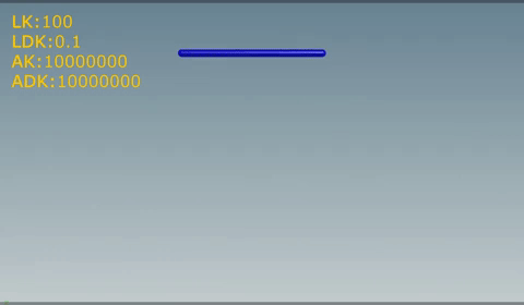
Fig.2
- Linear Damping Constant (LDK): This parameter make the stretching more soft (and slow) for higher values. Damping is a frictional force. Frictional forces are forces which have always an opposite direction to velocity.
Fig.3
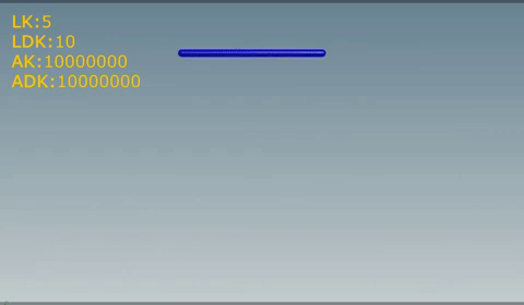
Fig.4
- Angular Spring Constant (AK): This parameter tells Houdini how much the wire is allowed to bend . Low values will allow the wire to be like a wire and move freely and oscillate. Higher values will give it some rigidity.
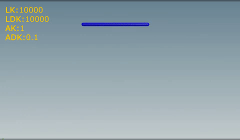
Fig.5
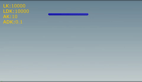
Fig.6
- Angular Damping constant (ADK): This parameter make the oscillation more soft (and slow) for higher values. Again it's a friction but this time for angular movements.
Fig.7
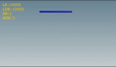
Fig.8
N.B.: The values I've used are just indicative. As for other things in Houdini there isn't an absolute high and low value. It depends a lot from the scene and in this case, from the correlation between this four parameters. For example: if the Linear Spring Constant is really high, the Linear Damping Constant will have almost no effects since it can't stretch anyway.
PLASTICITY:
For allow the Plasticity parameters to have effect on our wire we need to go to the Wire Solver node and turn on "Enable Plastic Deformation", otherwise even if we modify our plasticity parameters they are going to do nothing.
There aren't many objects in the real world that have plastic deformation on stretch, so I'll skip the first three for now. Anyway the concepts are the same as for the bend plasticity described below, just instead of bend plasticity it's stretch plasticity.
- Bend threshold (BT): This parameter says how much the wire has to bend for retain the bending deformation. If the bend exceed this threshold then the Bend Rate (BR) and Bend Hardening (BH) are applied. If the wire isn't bending enough then the other two parameters (Bend Rate, Bend Hardening) aren't going to be take in consideration.
The bending angle is not how much the wire is moving in space but it's the relative angle between the point and his neighbours points that are connected to it.
Here is an example using just the bend plasticity (so stretch rate is set to zero). A value of 3 in the bend threshold (BT) let the deformation happens just where the angle is greater than 3 (Fig.9). So when the points near the base of the wire exceed this values the Bend Hardening will take over and if it is high enough this points are going to become rigid and lose their elasticity. If you watch the upper part it never bends as much as the bottom and the hardening doesn't take place.
Using 0.5 in the BT (Fig.10) , the bend plasticity starts to take effect almost immediately and the wire looks more like a metal bar.
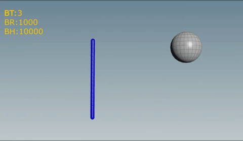
Fig.9
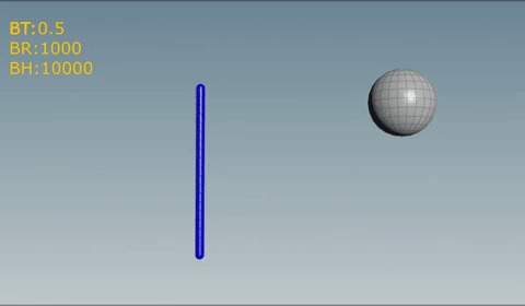
Fig.10
- Bend Rate (BR): This parameter says how fast the wire is allowed to retain the bending. If it's zero (as by default) it doesn't have any effect and the simulation will ignore the bend plasticity. It's strictly connected to the bend hardening and both parameters have to be adjusted for get the desired effect.
- Bend Hardening (BH): This says how hard the wire is after the deformation. It's easy to see what it does by doing two tests, one with 0 and the other one with a value a lot higher, for example 100. The effect on the wire is a lot similiar to the Angular Spring Constant.
03 – CREATING WIRES CONSTRAINTS
There are several ways to create constraints for the wires. My favourite is the following.
When you have a wire structure that is connected in some sort of hierarchy, the best option is to use multiple wireobjects in DOP.
I take a tree as an example. Each hierarchy has a different wireobject. We'll have big_branches, medium_branches and small_branches.
Using multiple wires object allows you to work and have the big branches to work as you wish. Then you can setup the medium branches and finally the small branches.
This allows you to work faster and also to easily use different parameters for different objects.
Also splitting the wire structure in multiple wire objects you can simulate faster than having just one wire object for everything.
Below you can find an example for setting up constraints with multiple wireobjects.